 Somerled
 StripForge

A KiCad plugin for laying out stripboard (Veroboard) circuits. You place your real footprints on the hole grid, and StripForge works out the strips, the cuts and the wire links from your netlist, checks the result with KiCad's DRC, and prints a build sheet to cut and solder from.
Beta. StripForge needs KiCad 10 and won't run on older versions. So far I've tested it on one real board, my ATtiny10 programming fixture (a 56 × 24 hole board). It works well there, but expect rough edges on other boards. Keep backups, check the DRC, and please tell me what breaks.
What it is
Stripboard is still the quickest way I know to build a one-off circuit you can solder. Laying it out usually means leaving KiCad for a separate program with its own parts library and its own idea of the circuit, and then the schematic and the build drift apart.
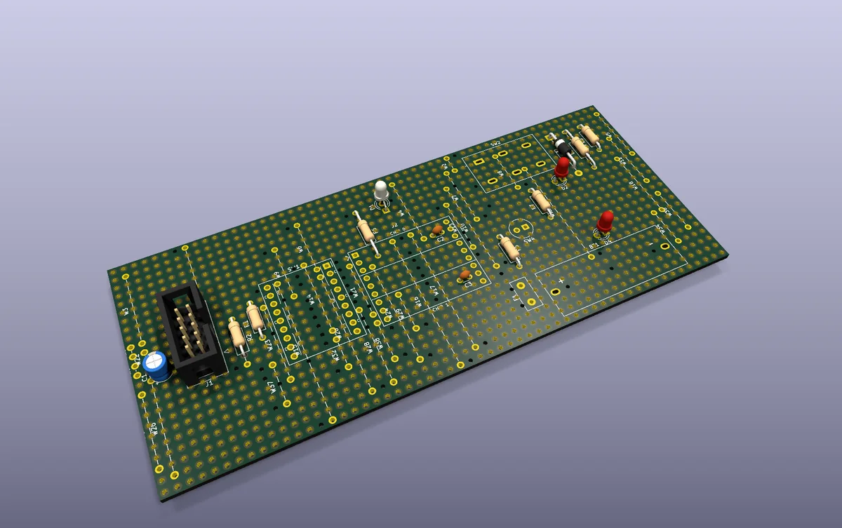
StripForge keeps the whole job in KiCad. It uses the footprints from your project, the schematic stays the source of truth, and what you get back is a normal .kicad_pcb whose copper is the strips. You can open it, edit it, run DRC on it and plot it like any other board.
Who it’s for
- People who draw their schematics in KiCad and build one-offs, prototypes, test fixtures and small kits on stripboard.
- Anyone who’d like the layout checked against the schematic before cutting copper, instead of finding the missing link with a meter afterwards.
- It isn’t for perfboard (pad-per-hole) or for routing real PCBs. For a PCB, just use KiCad as normal.
How it works
Place your through-hole parts roughly on the board’s 0.1" (2.54 mm) hole grid. After that, it’s five buttons in the PCB editor’s toolbar:

- Analyze is a read-only report of what it would do: how the parts snap, the cuts, the links needed, and anything that looks off.
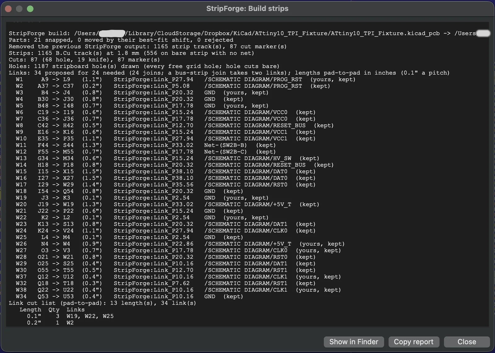
- Build strips saves and backs up the board, snaps each footprint to the nearest holes, splits the strips by net with cuts, adds wire links (
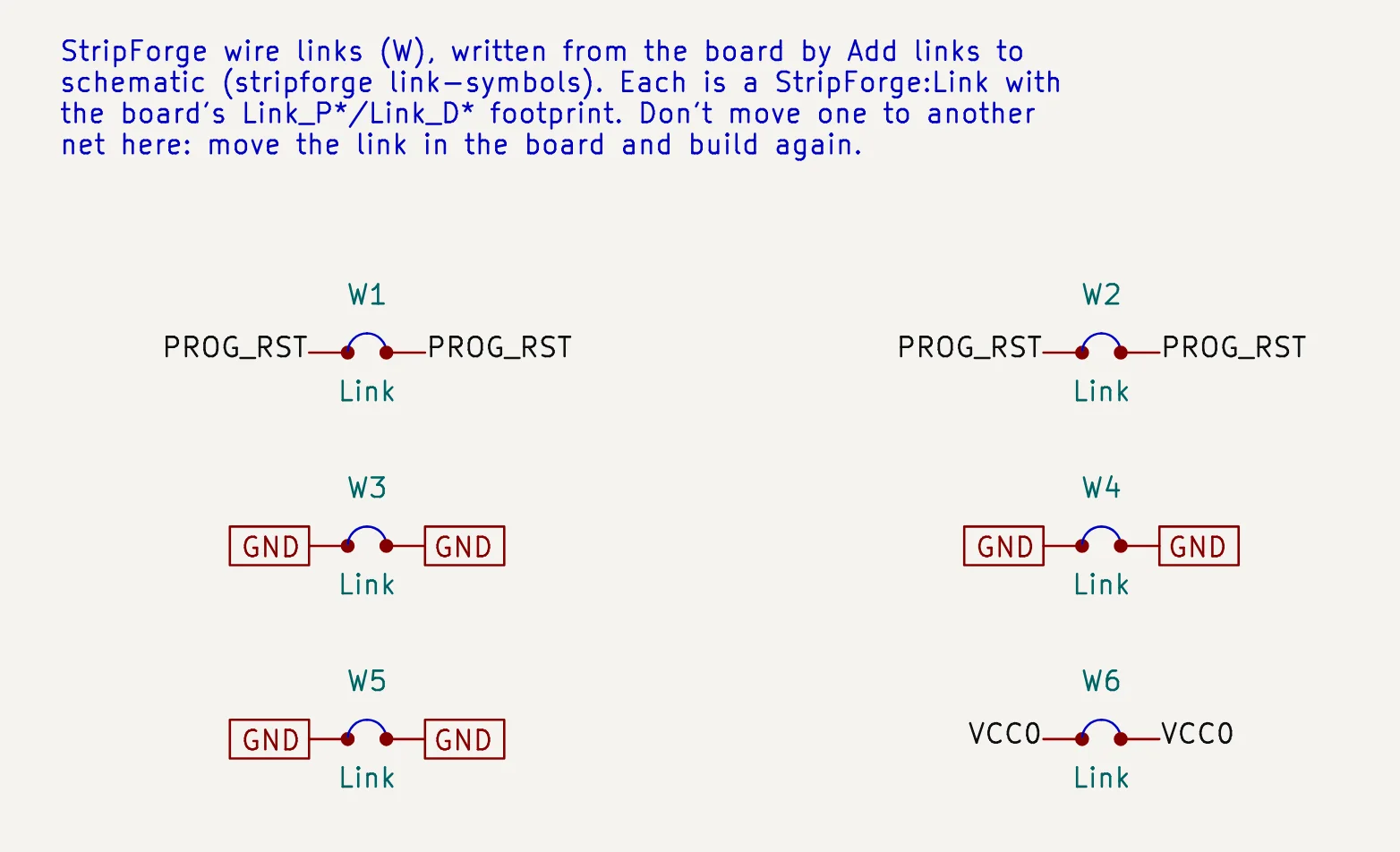
W1,W2, …) on their holes, and reloads the board. - Add links to schematic puts a link symbol in the schematic for each wire link, so that the schematic and the board stay in sync (then F8 updates the board as usual).
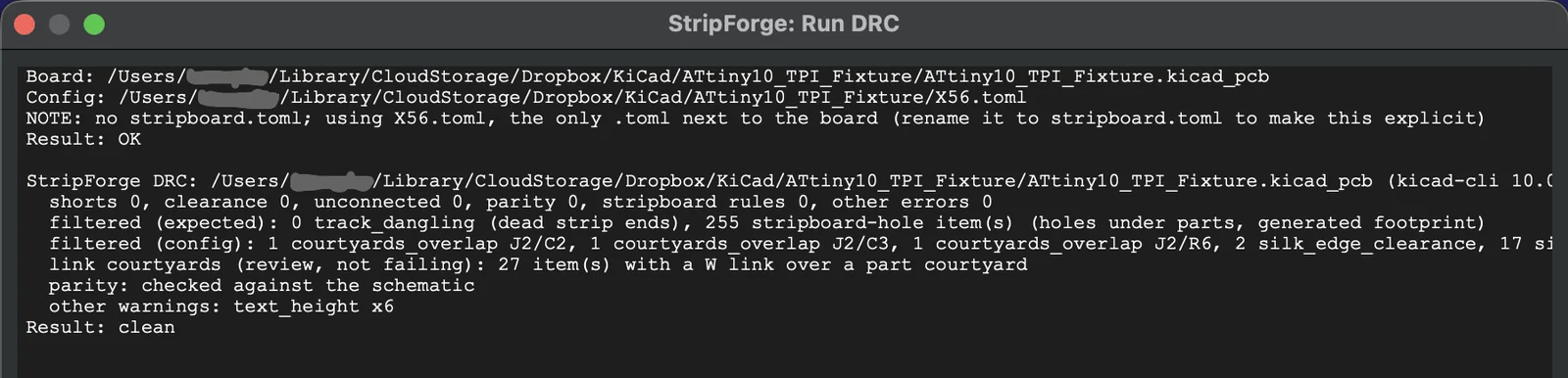
- Run DRC runs KiCad’s DRC with schematic parity and sorts the real problems from the noise every stripboard has. “shorts 0, unconnected 0” is what you want.
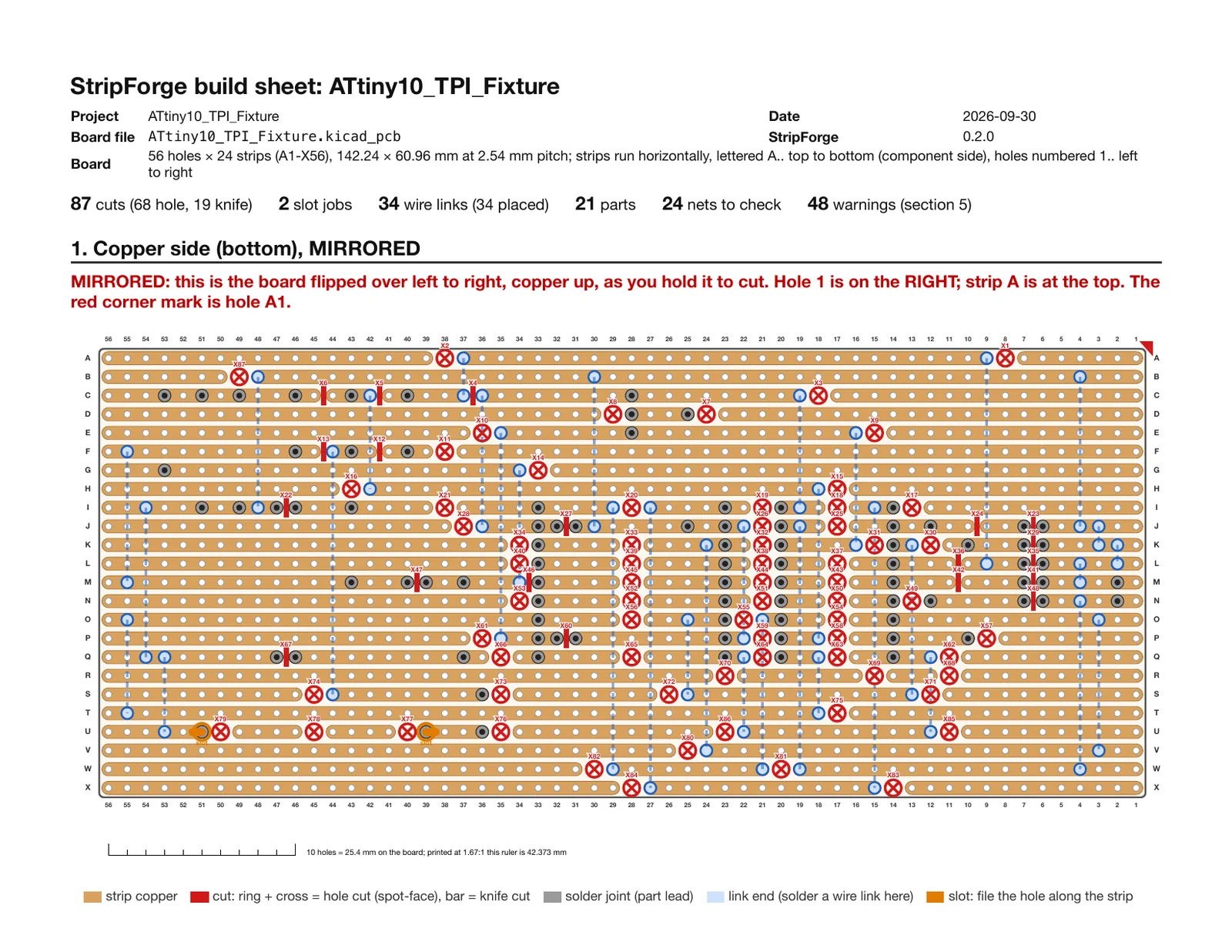
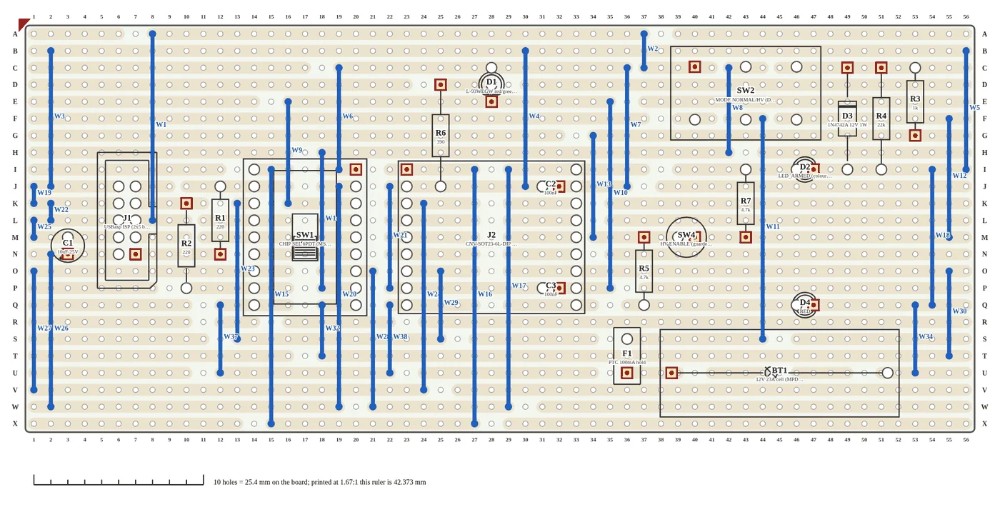
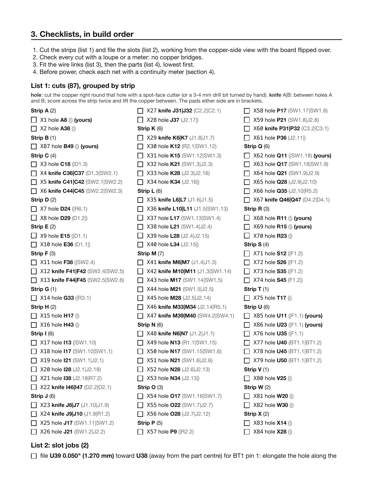
- Build sheet writes a printable sheet (HTML, and PDF if Chrome is installed): the copper side mirrored the way you hold the board to cut it, the component side, and checklists for every cut, link and part.
Changed your mind? Move parts, cuts or links and click Build strips again. It keeps the cuts and links you placed yourself and fills in the rest.
Features
- Real KiCad footprints. It uses the parts in your project, not a second parts library.
- A live netlist. A strip carrying two nets, a missing link or an extra cut shows up as a DRC error.
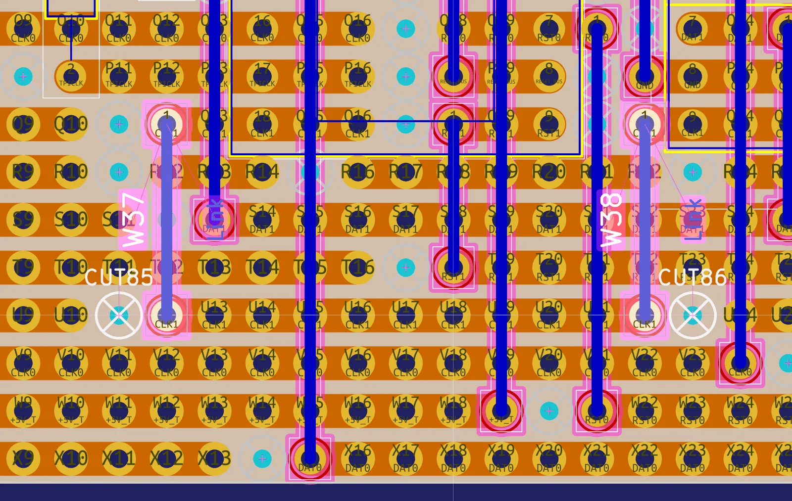
- Ordinary KiCad output. The strips are copper on B.Cu, the cuts are real gaps with a marker you can see and move, and the links are footprints.
- Wire links on both sides. Links go on the board and into the schematic, and a link cut list gives you the lengths.
- A build sheet you can work from. It shows mirrored copper, hole-cut and knife-cut marks, and checklists in build order.
- Nothing is overwritten without a copy. The board, the schematic sheets and the build sheet are backed up before each change.
- It also runs from the command line (
stripforge analyze | build | drc | sheet …), with no KiCad GUI needed.
Screenshots
These are from the ATtiny10 fixture.
Status and limits
- Beta (0.2.0). Tested with KiCad 10.0.4 on macOS, on one real board. I haven’t tried it on Linux or Windows yet.
- KiCad 10 only. It’s an IPC plugin, and it avoids the old SWIG
pcbnewAPI, which KiCad 11 removes. - Made for through-hole parts on a 0.1" (2.54 mm) stripboard grid.
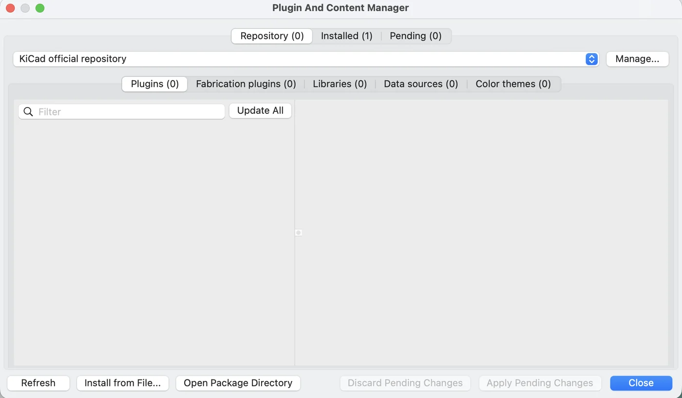
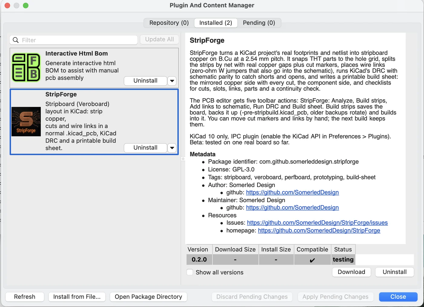
- Not in KiCad’s official Plugin and Content Manager yet. You install it from a zip file.
- Next on the list: more boards tested, pre-drilled mounting holes, and the official PCM.
Download and install
Releases go on the GitHub releases page. Version 0.2.0 isn’t tagged yet, so for now you can build the package from the repo with python tools/make_pcm_zip.py. In KiCad, open the Plugin and Content Manager, click Install from File…, and restart KiCad. The README has the full steps, including enabling the KiCad API and adding the StripForge footprint library.
Feedback
If you try it, I’d like to hear how it went, good or bad, especially on boards that aren’t mine. Please open an issue on GitHub. If you can, attach the board and schematic (or a cut-down copy) and the report text.
License and credits
StripForge is free software under the GNU General Public License, version 3 or later (GPL-3.0-or-later). It comes with no warranty. See the LICENSE. Copyright © 2026 Somerled Design.
- perfboard-studio (Apache-2.0) inspired StripForge. Its stripboard model (strips split into segments at the cuts), connectivity checks and build guide shaped the design.
- VeroRoute, VeeCAD and DIYLC are the stripboard and layout tools that came before. I’ve credited them for ideas only; no code is taken from them.
- It’s built on KiCad: its IPC API,
kicad-cliand DRC.